This release also includes additional features that improve the overall toolpath and simulation products offered by ModuleWorks.
Toolpath
Multi-Axis Surface Finishing |
Geodesic Machining
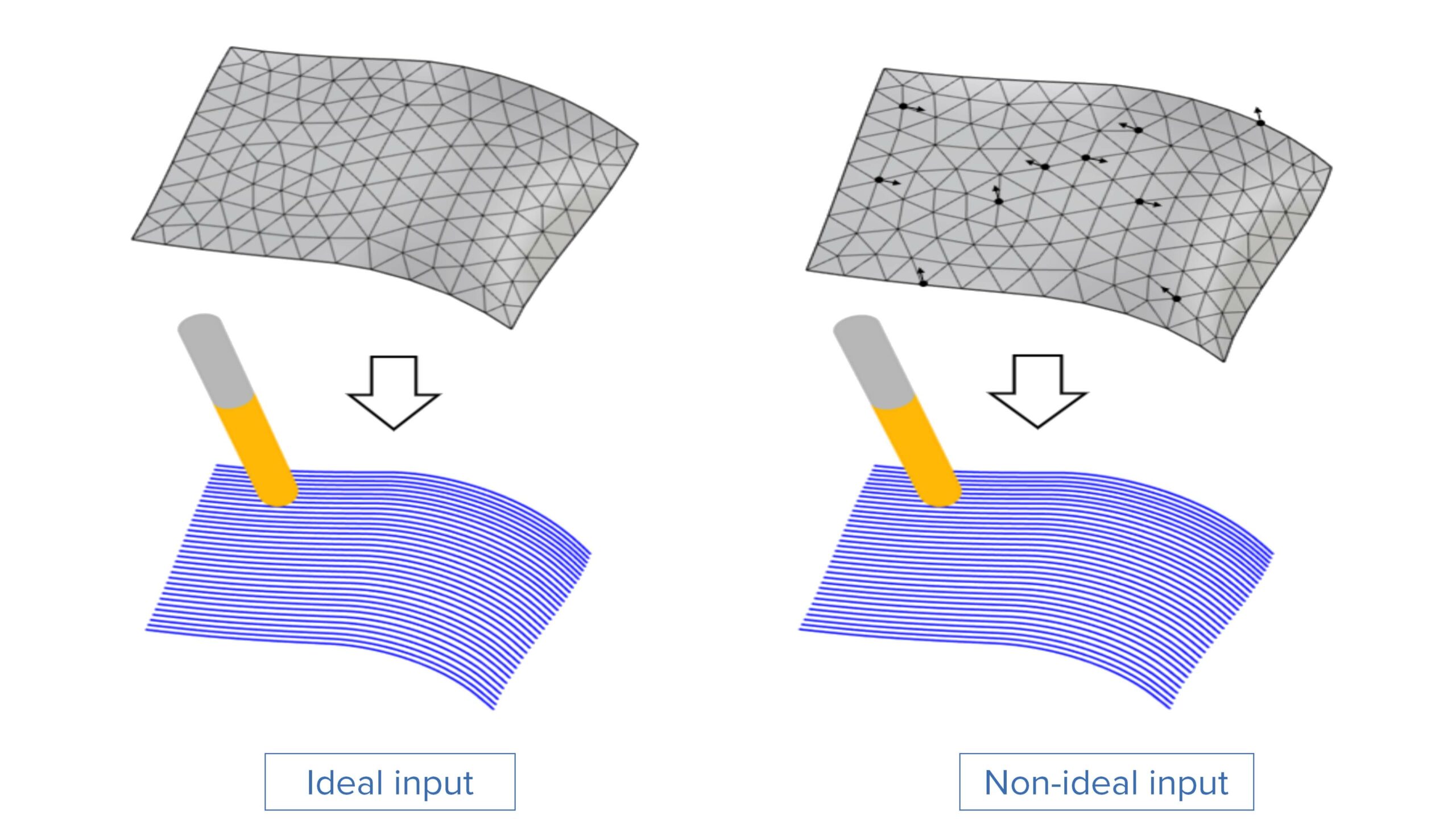
Robustness against Input Deviation
Challenge: Small changes in the meshes (new triangulation, different mesh offset, different mesh patching), can significantly affect the machining paths.
Solution: This enhancement makes current toolpaths more robust to small input deviations.
Benefits: This enhancement gives users more control over the toolpath generation.
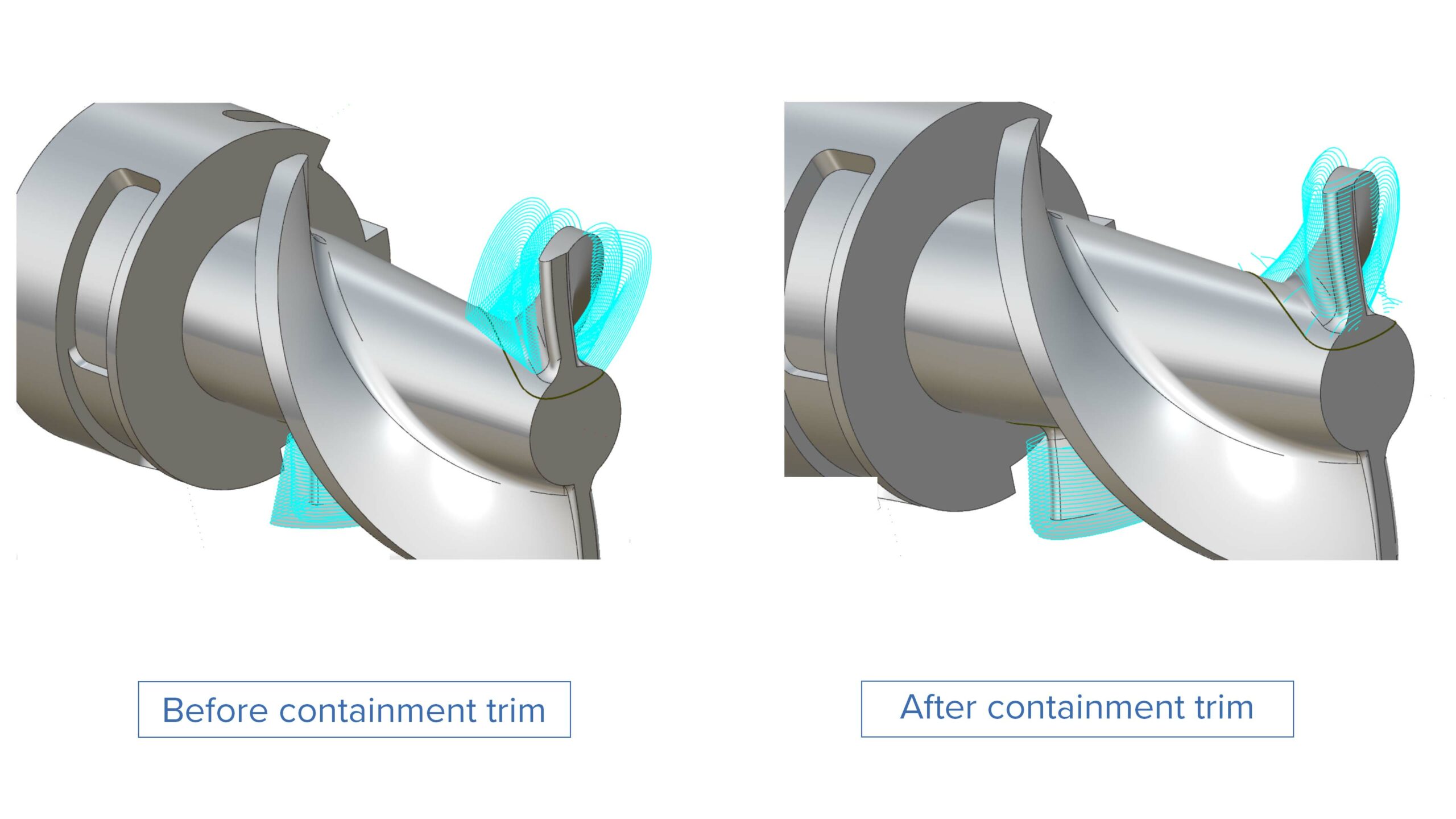
Challenge: The toolpath in a containment is designed to the reach the boundaries of the containment to ensure that material is removed. However, when finishing, the user may add the boundary and expect no toolpath to be added.
Solution: The user has the option to trim the toolpath and no extra cutting passes are created.
Benefits: This allows users to tailor the toolpath to benefit from the containment function.
Special Parts |
Multiblade
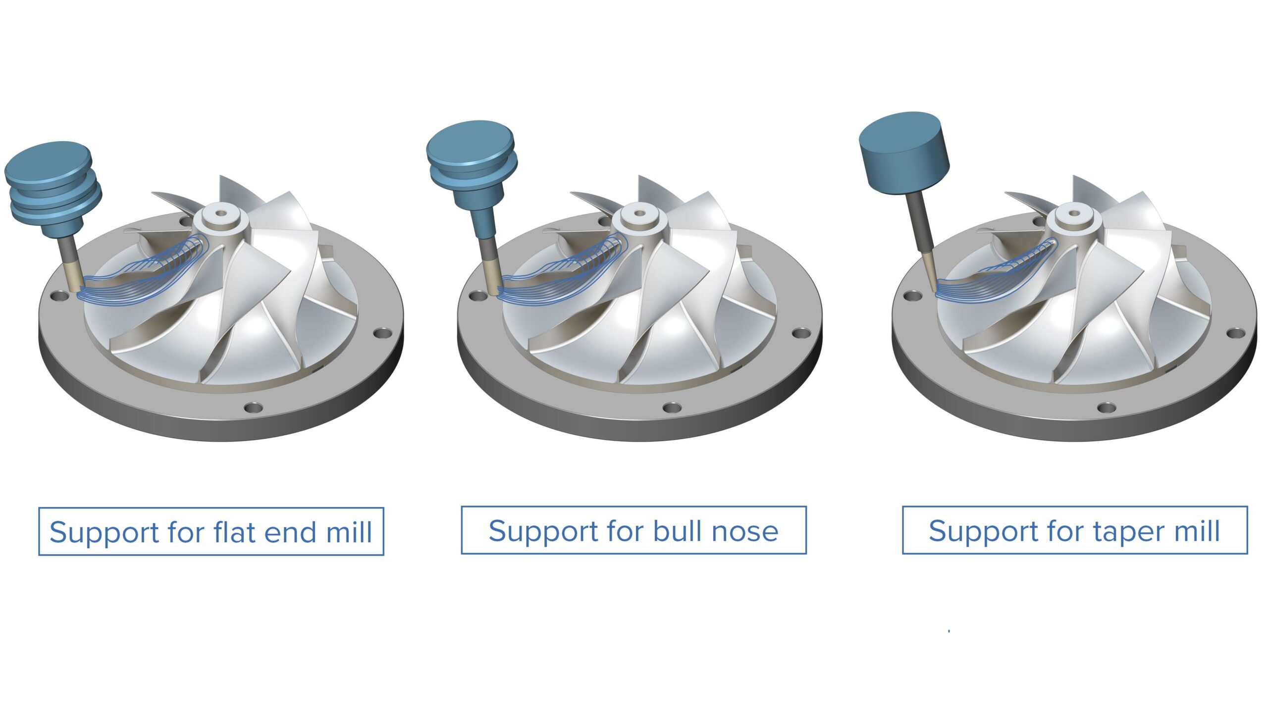
Expanded Tool Support for Blade Finishing
Challenge: Multiblade finishing is currently only possible with ball end mills and barrel mills when machining blisks. This limits users and prevents them from using standard tools such as flat end mills and bull nose mills.
Solution: It is now possible to use bull nose mills, end mills, and all types of taper tools for blade finishing.
Benefits: This enhancement gives users more machining flexibility to use standard tools such as bull nose mills for multiblade finishing.
Special Parts |
Multiblade
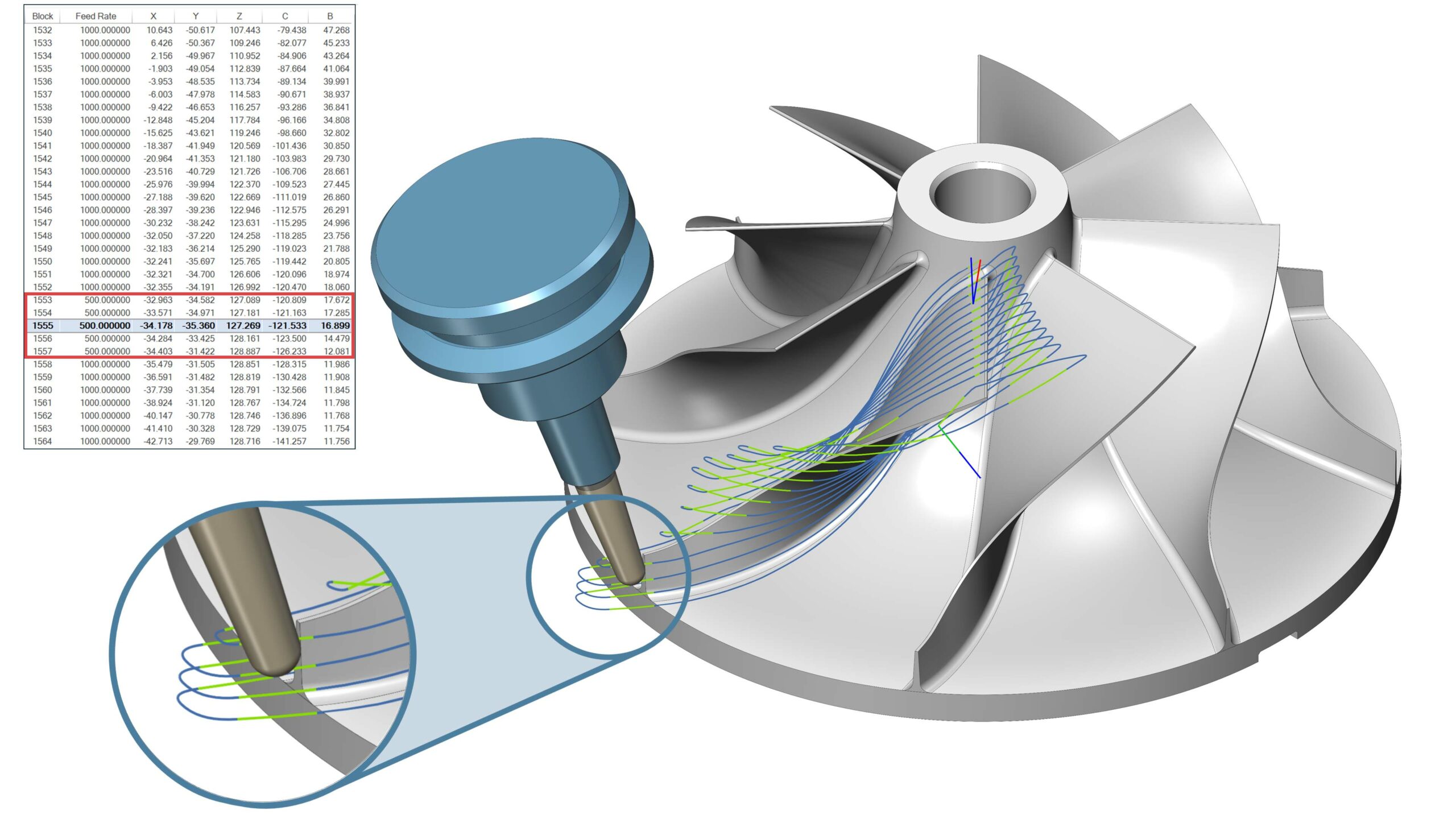
Control Feed Rate on Edge Extensions
Challenge: When applying extensions to the leading or trailing edge, the aim is to leave offset material to finish later. Therefore, since the extension is not going to actively cut the material, it makes sense to increase the feed rate to save machining time.
Solution: The feed rate (%) parameter, which currently only modifies the feed when the tool touches the blade, has been expanded and now also applies to the extensions.
Benefits: It is now possible to use a faster feed rate for leading and trailing edge extensions, reducing the overall machining cycle time.
3-Axis Machining |
3-Axis
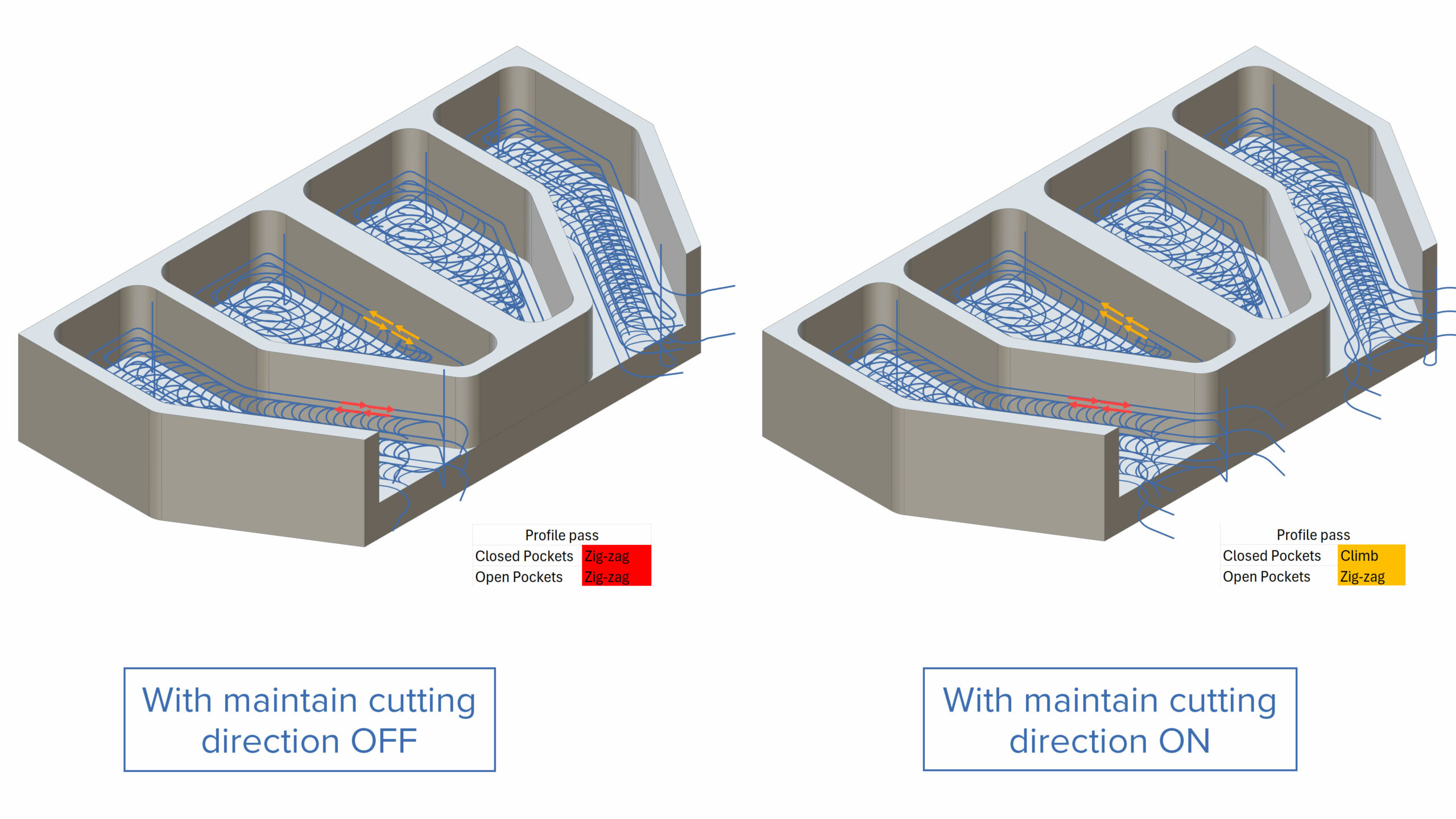
Maintain Cutting Direction for Closed Profile Passes
Challenge: Failure to maintain the cutting direction in closed profile passes can generate a poor surface finish because zig-zag moves are applied by default. For open contours, it can be even worse, causing significant retracts and air motions.
Solution: A new option helps to maintain the cutting direction. It applies one-way machining to the profile pass on closed contours, while respecting the climb/conventional option. For open contours, the zig-zag motion is performed on the profile pass.
Benefits: This enhancement improves the quality of the machined surface while reducing the link length and machining time.
3-Axis Machining |
3-Axis
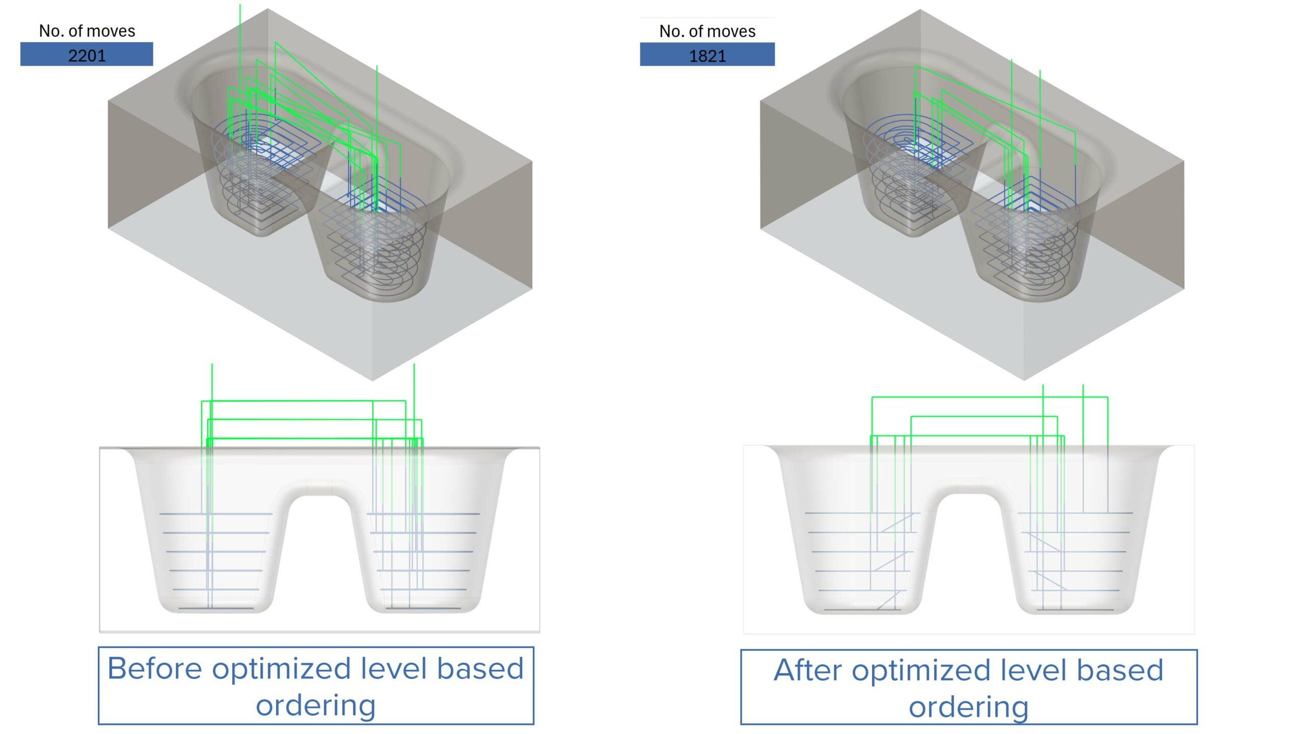
Optimized Level Based Ordering
Challenge: Currently, ModuleWorks follows strict level based ordering for parts with multiple pockets on regions. This can result in unnecessary retracts and increased machining time.
Solution: The new optimized ordering reduces the link motions between regions while keeping level based ordering.
Benefits: This reduces air machining and therefore total machining time while using level based ordering for the roughing toolpath.
2-Axis Machining |
Hole Making
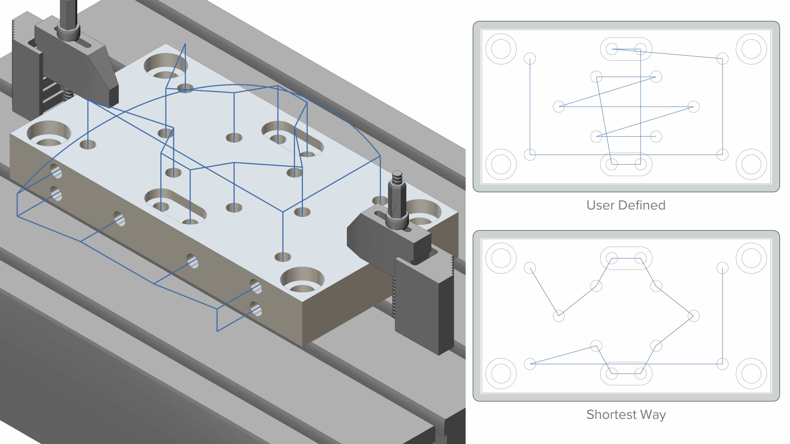
Ordering
Challenge: Non-ordered hole making operations cause a lot of unnecessary movements, resulting in longer machining times.
Solution: Ordering is now possible for hole making operations.
Benefits: Ordering reduces cycle times for hole making operations due to shorter linking movements.
Turning | Turning/PrimeTurning™
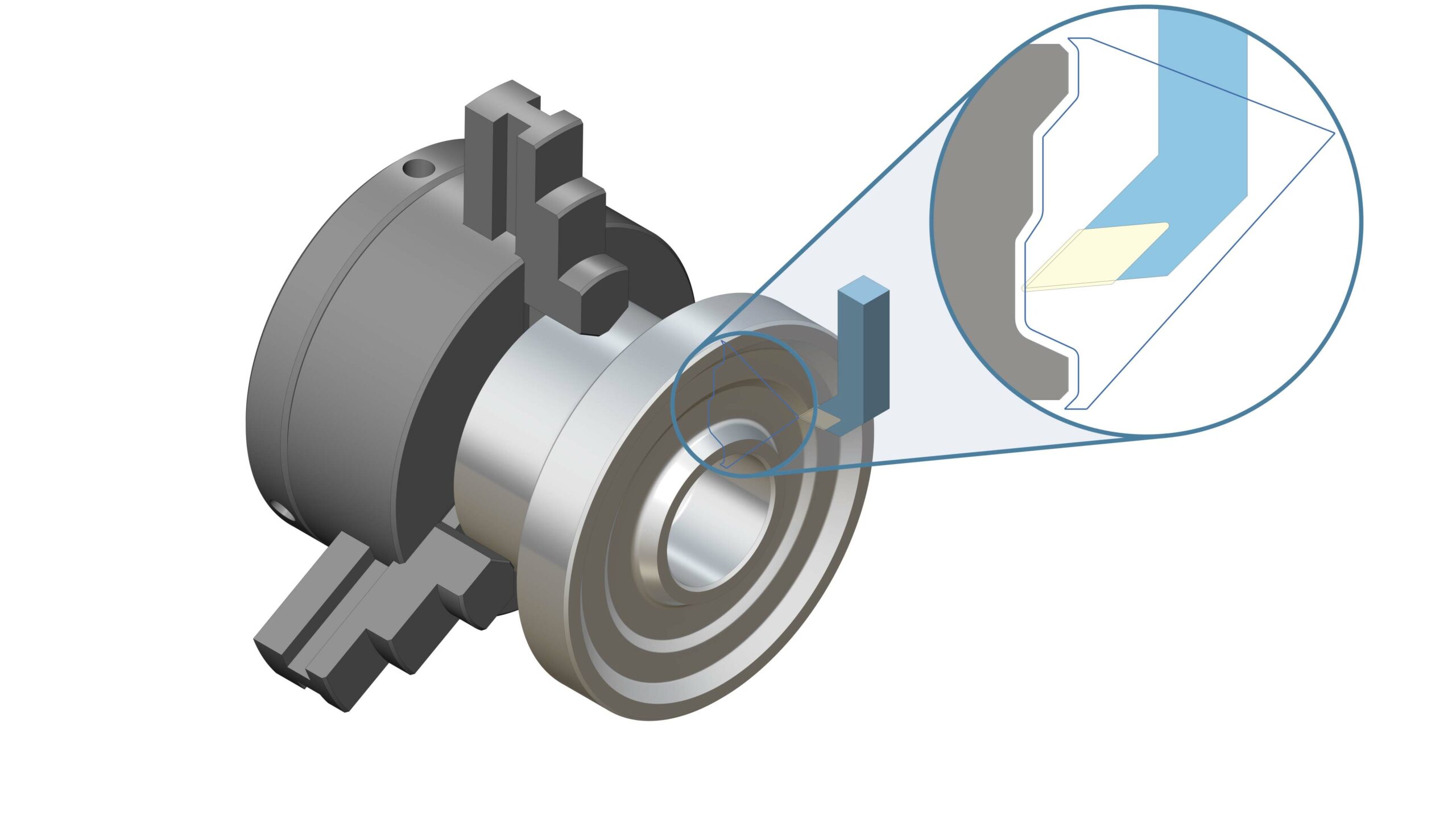
Profile Finish Toolpath on Face Side
Challenge: Users do not have an option to finish a non-flat profile on the face side of part.
Solution: With this new feature, users can now create a profile finish toolpath on the face side of the part.
Benefits: This is especially useful for finishing non-flat faces on the face side of the part.
Turning | Turning
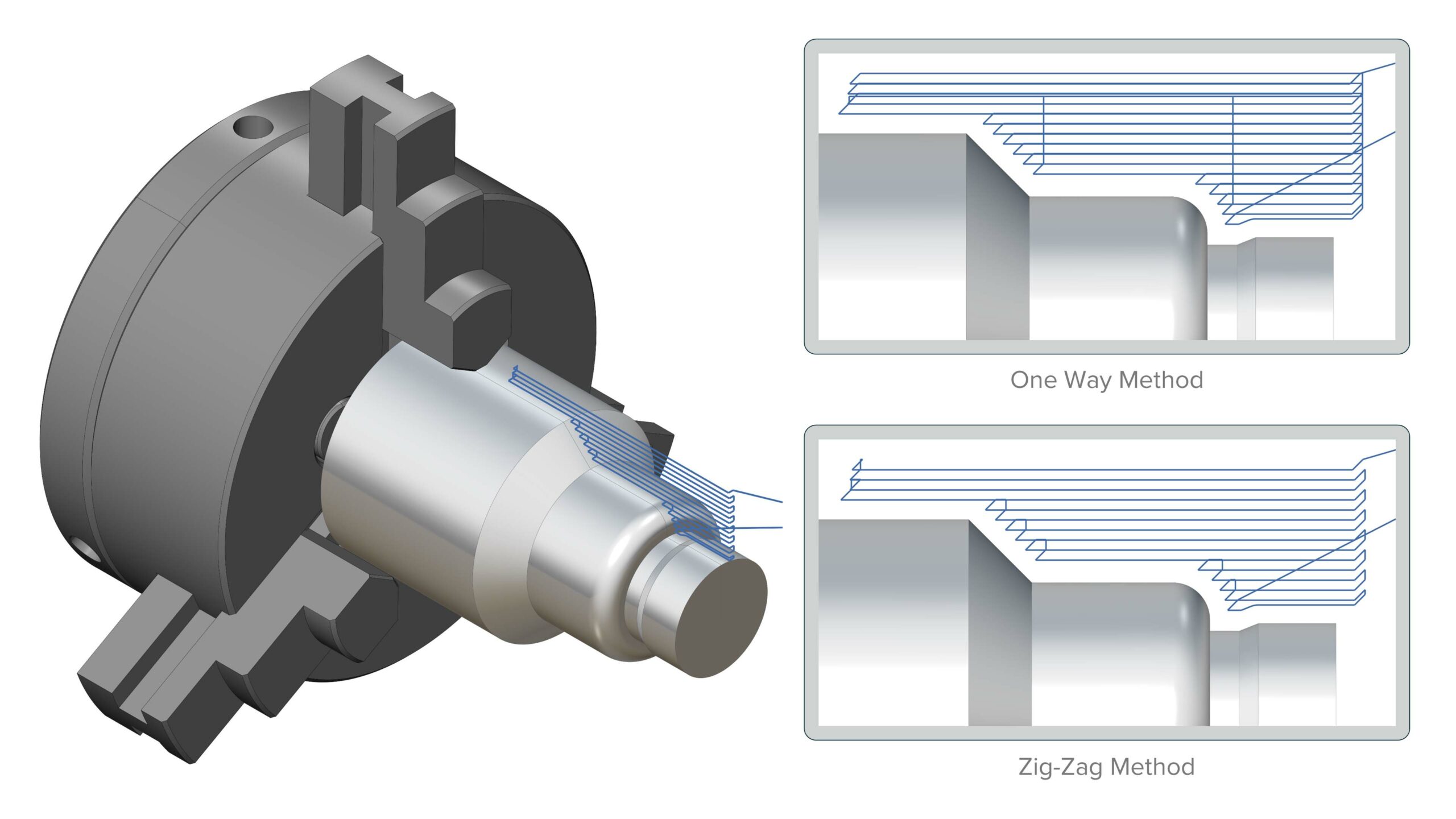
Zig-Zag Cutting Method for Roughing
Challenge: Users are unable to create zig-zag toolpath with turning inserts which are capable of multidirectional cutting.
Solution: Rough turning now supports the zig-zag cutting method.
Benefits: The pattern is useful for adaptive turning toolpaths where inserts are capable of machining in both directions. This pattern reduces machining time as non-cutting moves are reduced. Inserts are also utilized optimally.
Turning | PrimeTurning™
Support for Second Generation PrimeTurn B-type Insert
Challenge: Currently, users are not able to use the second generation PrimeTurn B-type insert.
Solution: Users can now define and use a second generation PrimeTurn B-type insert with corner radii of 0.8 and 1.6. The insert geometry is added in the ModuleWorks database.
Benefits: Users can leverage the second generation PrimeTurn B-type insert for more efficient machining.
Additive | Fused Deposition Modeling
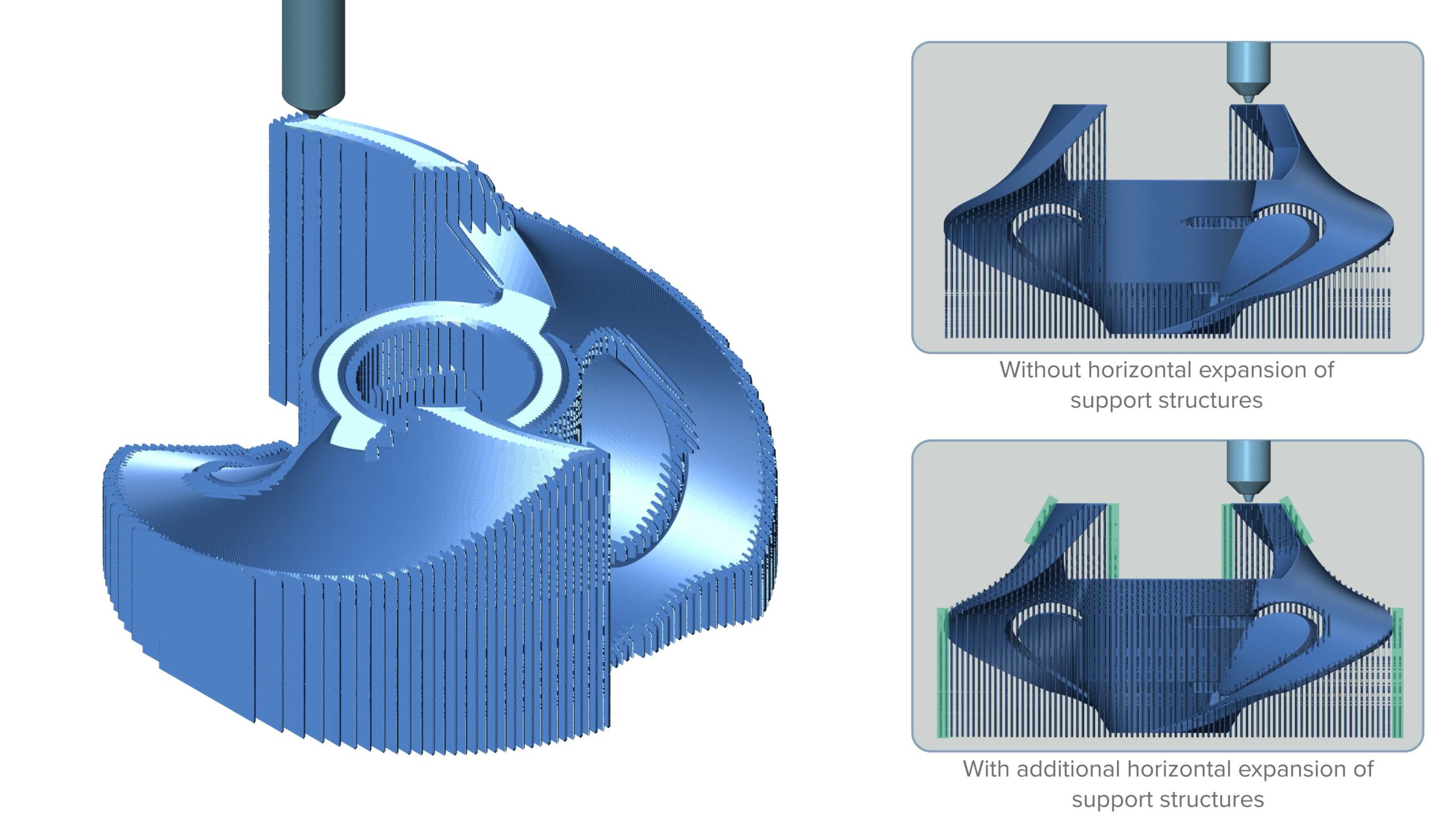
Horizontal Expansion for Support Structures
Challenge: In certain scenarios, such as areas with steep walls, the support structures need to be extended to provide better support.
Solution: Users can now offset the support structure by a user-defined value.
Benefits: Steep walls, extreme overhangs, and over-welded areas can be supported and printed stably without any issues.
Additive | Fused Deposition Modeling
List of Angles to Rotate Infill Pattern Layer by Layer
Challenge: Users often need to rotate the infill pattern not only by one fixed angle, but by different angles layer by layer.
Solution: It is now possible to rotate every layer by a user-defined angle increment.
Benefits: Improved layer adhesion results in, for example, more stiffness in the part. In solid filled layers, it can reduce the number of cavities.
Additive | Fused Deposition Modeling
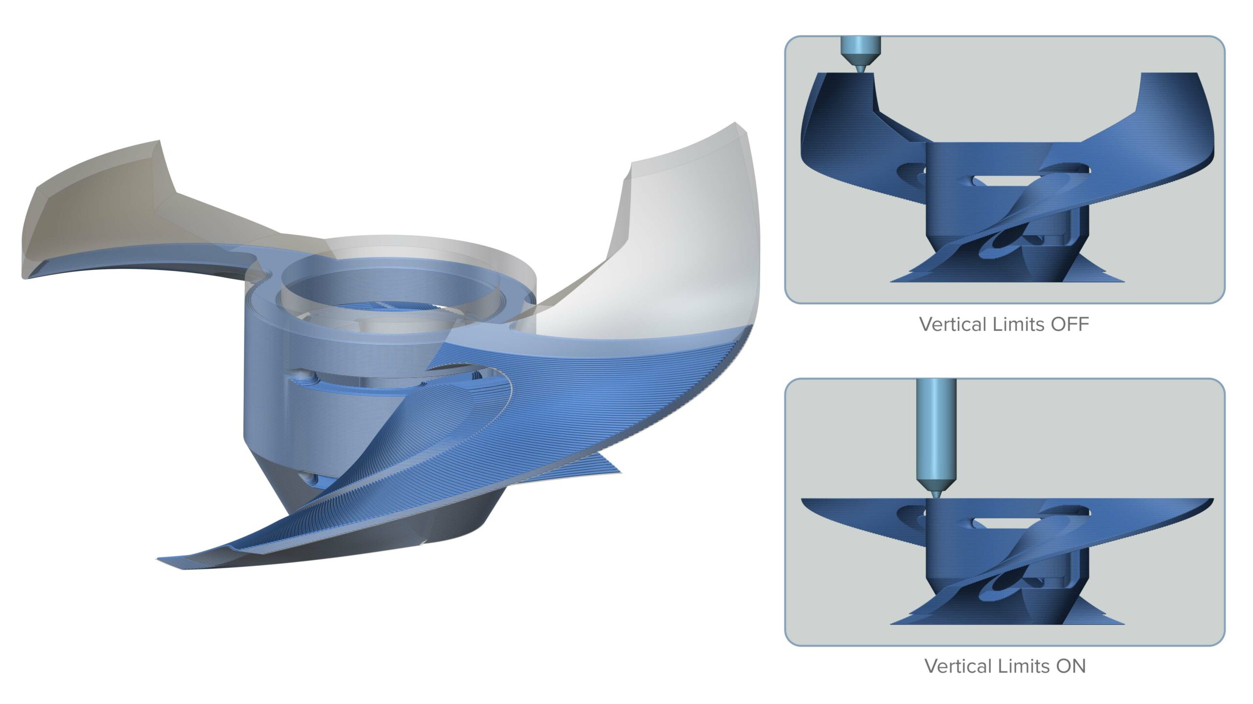
User-Defined Height Range for Calculation
Challenge: The user does not always want to calculate the entire part just to see whether the correct parameters have been selected.
Solution: It is now possible to reduce the preparation area of the part to a defined height range, and to run the calculation for this defined range only.
Benefits: This reduces the overall calculation time as only an area of the part is used for quick pre-visualization and to ascertain whether the parameters would work for the entire part.
Additive | Fused Deposition Modeling
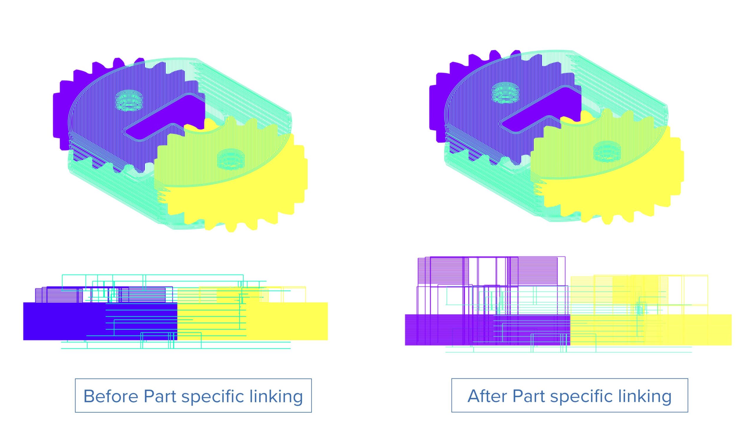
Part Specific Linking Options
Challenge: It is difficult to build multiple parts with part-specific linking options in one production job as all the parameters, including linking, can only be set globally.
Solution: There is now an option to apply part-specific linking in one job.
Benefits: This enhancement enables users to tailor links to the shape of the part. This accelerates production and reduces drops of excess material underneath components by having the right amount of retracts.
Core Component Technologies |
Tilting Core
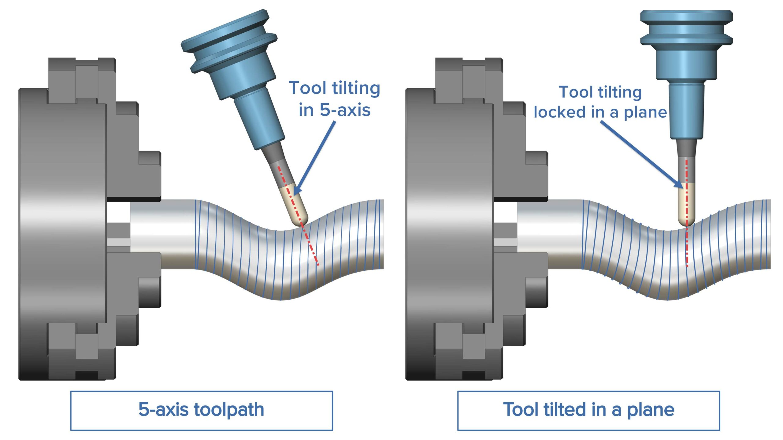
Tilt Tool in a User Defined Plane
Challenge: It is currently difficult to limit tool orientation changes to a single rotation axis while keeping the other axes fixed.
Solution: A new tilting strategy has been added. The tool axis can now be tilted in the plane defined by the normal to a user-selected direction. The tool axis is projected on the selected plane on each toolpath point. If the plane normal is aligned with one of the machine’s rotational axes, it will limit rotational machine movements to that axis.
Benefits: User-defined tool tilting results in fewer machine axis movements and more stable machining.
Core Component Technologies |
Linking
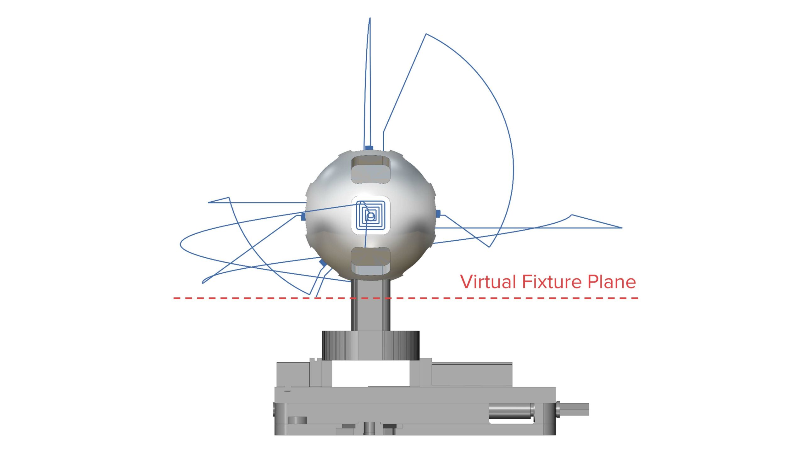
Virtual Fixture Plane for Safe Linking
Challenge: When the machining environment, including fixtures and part geometries, is not specified completely, the generated links can easily run through these geometries, especially when spherical clearances are used.
Solution: There is now an option to define the fixture plane according to a user-specified height so that links are forced to stay above that plane.
Benefits: Defining the fixture plane reduces the risk of collisions, even on complex machining setups.
Simulation
Simulation SDK | CNC Simulation
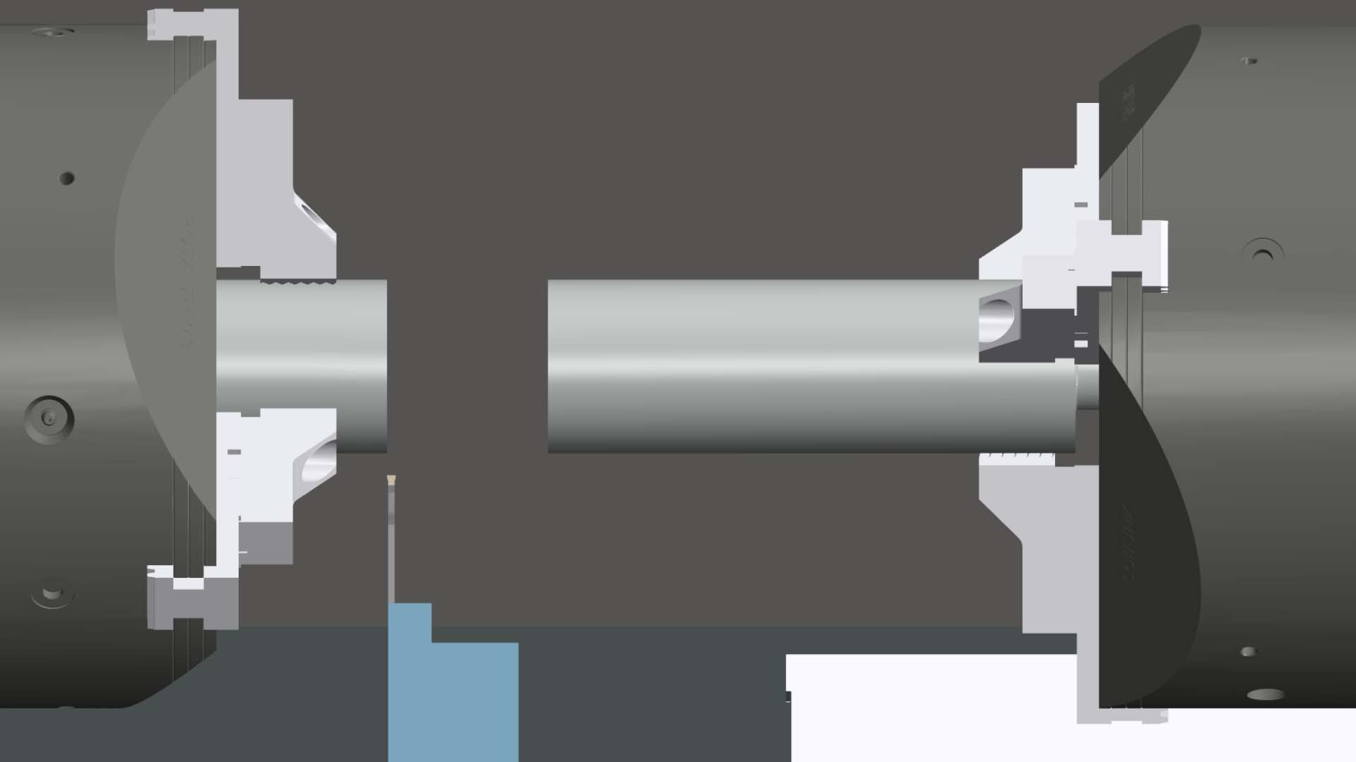
Cut-Off and Handover
Challenge: The simulation of stock handling processes such as cut-off and handover is essential for fully verifying operations and programs for lathes and mill-turn machines. However, implementing this functionality in simulation solutions is often complex.
Solution: CNC Simulation now provides mechanisms for easily implementing stock-handling between multiple workpiece spindles, including manual or automatic cut-off detection.
Benefits: With the CNC Simulator, it is now easier to verify operations and programs, including part handling for lathes and mill-turn machines.
Simulation Systems | NC Editor
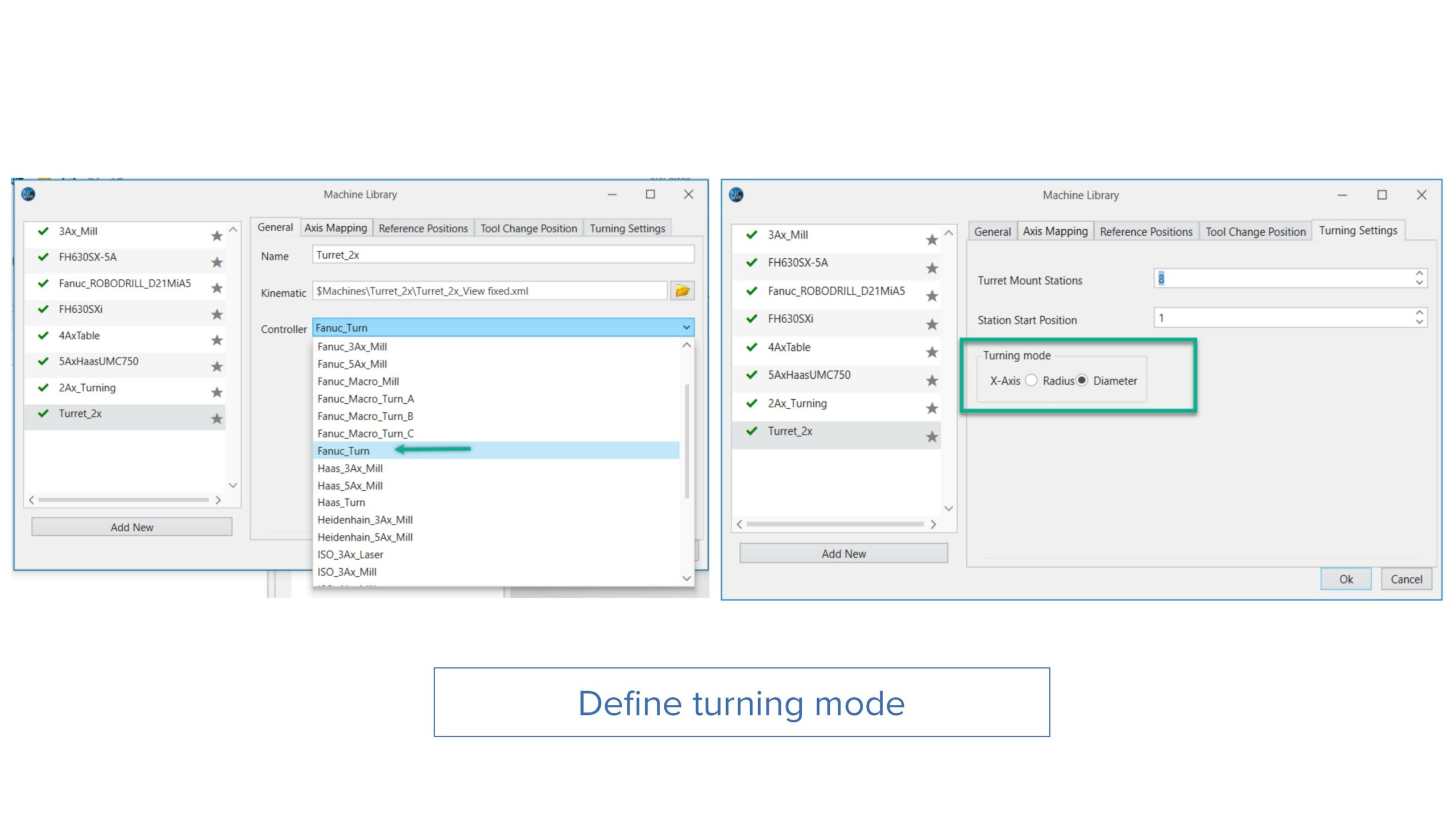
Ability to Define Diameter or Radius Mode for Turning
Challenge: Users currently need two separate controller files for the diameter and radius mode settings, which causes unnecessary confusion.
Solution: Users can now specify a Diameter/Radius turning mode in the controller settings on the Turning tab.
Benefits: With this enhancement, users can easily access the machine controller settings to switch between turning modes, eliminating multiple files and simplifying operation.
Simulation Systems | NC Editor
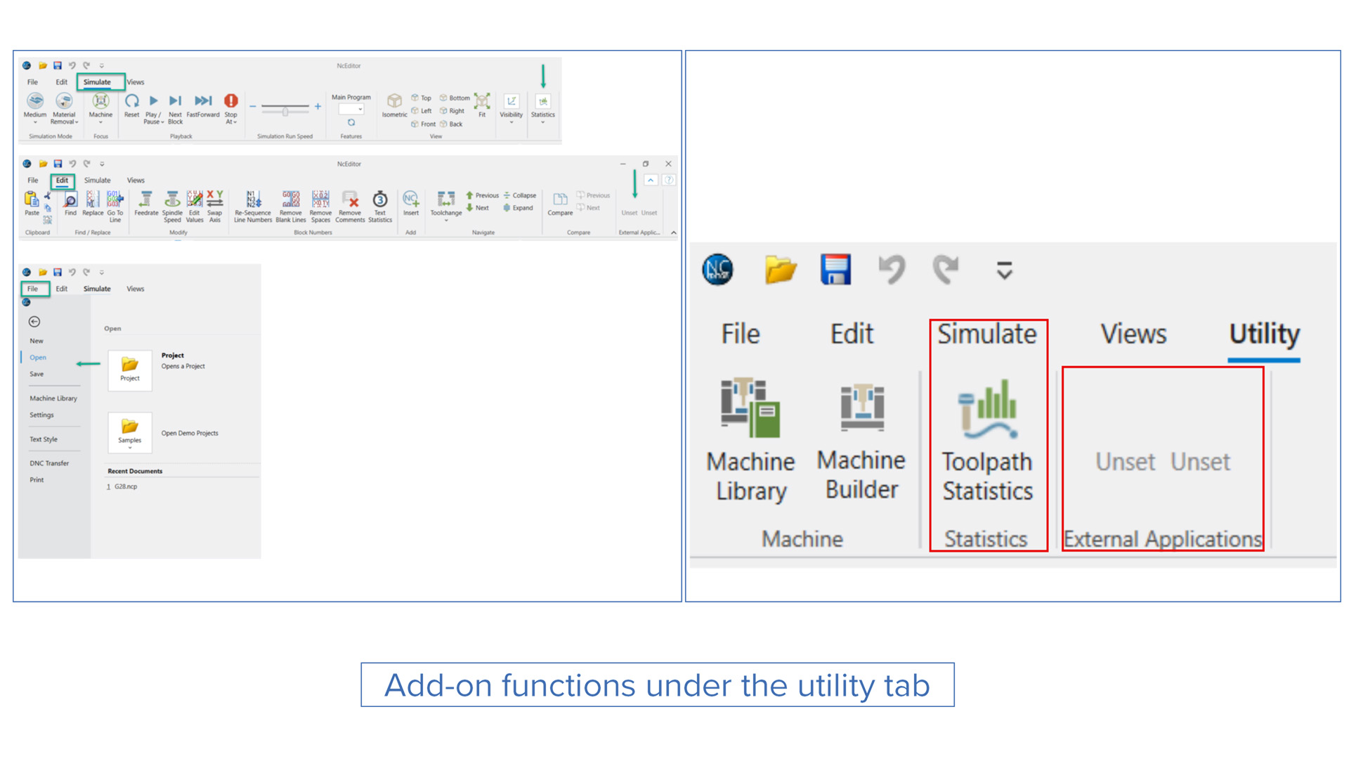
Add-On Functions under the Utility Tab
Challenge: Currently, users have to search for toolpath statistics, connections and machine libraries on different toolbars. This creates unnecessary confusion and extra effort for users.
Solution: Now, all the add-on functions are located on the Utility tab of the NC Editor interface.
Benefits: This enhancement significantly improves the user experience.
Simulation Systems | NC Editor
Display True Shape of Threads in Simulation
Challenge: It is difficult for users to differentiate between regular turning and threading operations.
Solution: NC Editor can now display the true shape of threads for threading operations during a simulation. This is achieved by synchronizing the axis during the feed movement with the rotational axis to create a threading simulation.
Benefits: By simulating and displaying the true shape of threads, NC Editor offers a highly accurate, “real-life” simulation.
Simulation Systems | NC Editor
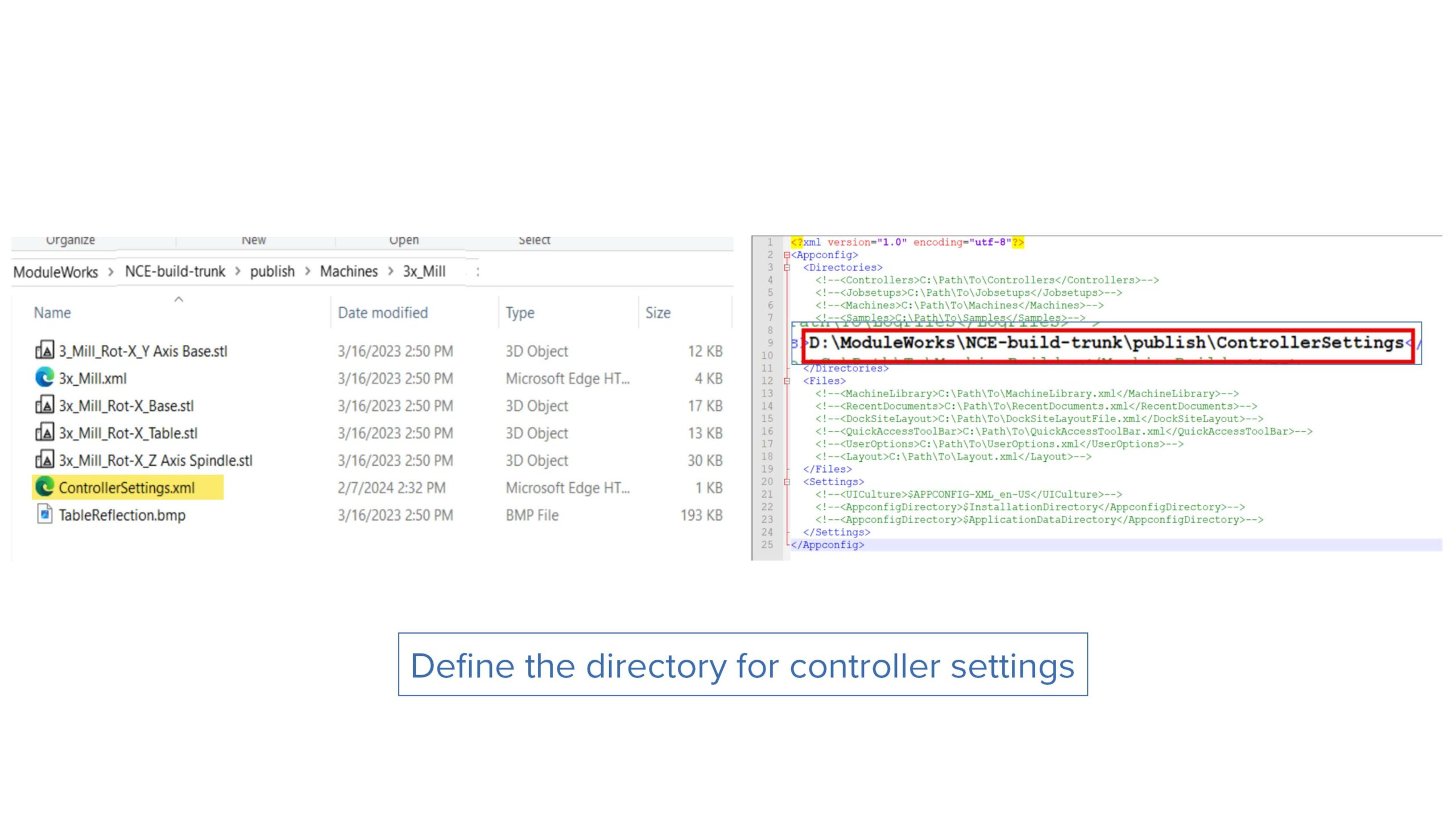
Ability to Define Directory to Store Local ControllerSettings.xml
Challenge: Currently, it is not possible to create multiple machines using the same kinematic file because the controller setting file is saved in the machine kinematic directory.
Solution: Now, controller settings are saved separately in a specified path in a directory named after the machine name.
Benefits: This feature allows users to create multiple machines from existing kinematic files using different ControllerSettings.
Simulation Systems | NC Editor
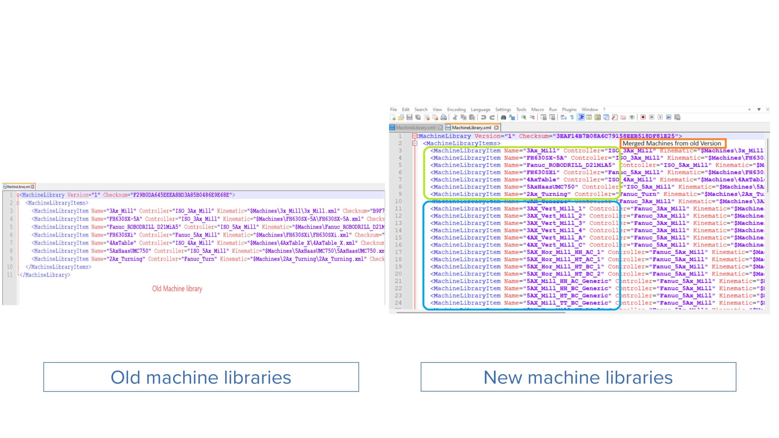
Ability to Merge Old and New MachineLibrary
Challenge: Currently, when the old MachineLibrary file is updated, it gets overwritten, which means existing data is lost.
Solution: Now, when upgrading to a newer version, the integrator renames the MachineLibrary with a .bak extension. After backup, the application merges the old and new MachineLibrary.xml files and updates the information.
Benefits: Users retain all the data from their old MachineLibrary when they upgrade to a new version, making it easier and faster to upgrade.